1 / 1
Note: In case the above normal operating conditions are exceeded, users may consult and confirm with the manufacturer.
| Item | Unit | Parameter | |
|---|---|---|---|
| Rated Voltage | kV | 40.5 | |
| Maximum Rated Current | A | 2000 | |
| Rated Breaking Current | kA | 25 | 31.5 |
| Rated Making Current (Peak Value) | kA | 63 | 80 |
| Peak Value of Limiting Through Current | kA | 63 | 80 |
| Rated Short-time Withstand Current (4s) | kA | 25 | 21.5 |
| Conventional Overall Dimensions (W×D×H) | mm | 1918*3250*3125 | |
| Protection Class | - | IP2X | |
| Weight | kg | About 1500 | |
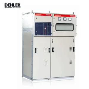
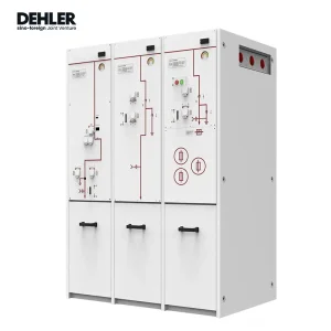
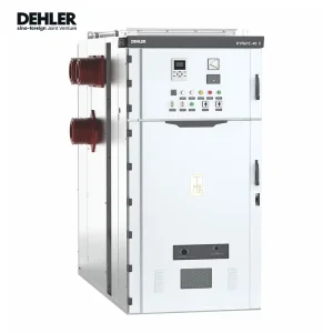
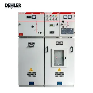
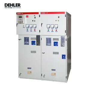
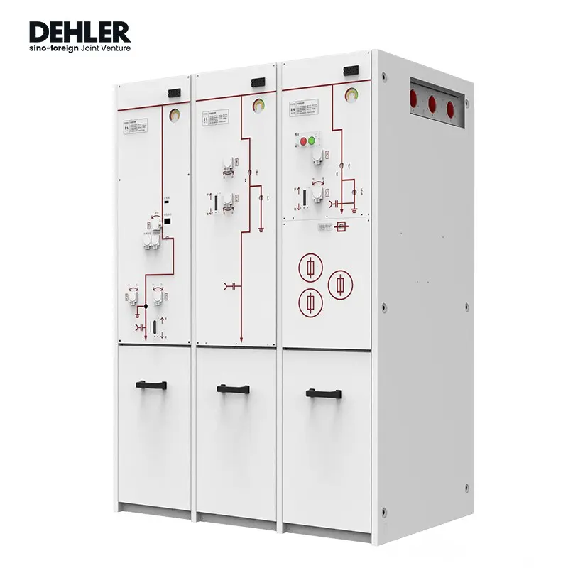
The XGN-40.5 Box-type Fixed AC Metal-clad Switchgear adopts a fixed structure. Its basic frame is fabricated by welding bent section steel and steel plates, and the cabinet enclosure meets the IP2X protection class. This switchgear is mainly assembled from a front cabinet and a rear cabinet, with corresponding functional units configured according to different applications. Air insulation is primarily used between live parts inside the cabinet, and the insulation distance between all live parts, as well as between live parts and ground, is not less than 300 mm.
The front cabinet houses a main busbar & busbar disconnector compartment, a circuit breaker compartment, and a relay compartment. The main busbar & busbar disconnector compartment is located at the upper part of the cabinet, while the circuit breaker compartment is at the lower part and also accommodates current transformers. The two compartments are separated by an insulating plate and connected via busbar bushings. Relays are installed in the middle of the front face of the cabinet, with 15 sections of auxiliary busbar terminals and a two-core cable channel provided. The terminal compartment is inside the lower left small door, which can fit more than 80 JH10-type terminals. An M12 grounding bolt is installed at the bottom of this compartment for auxiliary circuit grounding, and the right small door serves as a maintenance access. An operation panel is positioned above the terminal compartment, which can be fitted with auxiliary switches.
The rear cabinet is connected to the front cabinet via bolts. It can be equipped with a bypass busbar and disconnector as required, and overhead incoming/outgoing lines also pass through this cabinet. When a bypass busbar is installed, if the overhead lines do not reach the safe height, an additional small auxiliary cabinet or protective barrier must be added. Without a bypass busbar, overhead lines can pass through the top of the rear cabinet. This cabinet can also be fitted with voltage transformers or lightning arresters, and tie busbars and cable outgoing lines are installed here. The rear door features a double-door structure; if the live-line indicator shows no voltage, the rear door can be opened. The main busbar compartment is separated from the rear cabinet by a partition.