
Dehler Dehler

How to Choose the Right Lightning Arrester?

Time:2026-10-17 Author:Madeline
0%

Choosing the right Lightning Arrester is not a simple matter of selecting the highest voltage rating. It requires a practical review of the electrical system, exposure level, grounding quality, and equipment sensitivity. A device installed beside a transformer faces different stress than one protecting a rooftop control panel. Cable length matters. So does the distance between the arrester and the equipment.

Lightning researcher Martin A. Uman described lightning as “a giant electrical spark.” That image matters because the event is brief, powerful, and unpredictable. A suitable Lightning Arrester must respond quickly while carrying surge energy safely to ground. Its continuous operating voltage should match the system. Its nominal discharge current should reflect expected surge conditions. Its energy capability should suit the installation environment.

Look closely at the details.

A dusty substation, a coastal facility, and a data center do not share the same risks. Check coordination between arresters. Confirm the grounding path is short, direct, and mechanically secure. Inspect the manufacturer’s test data, not only the product label. Standards such as IEC 60099-4 can support a reliable technical comparison.

Still, no selection method is perfect. Field conditions often differ from design assumptions. An arrester can be correctly rated yet poorly installed. That weakness is easy to miss.

This guide explains the key decisions, common mistakes, and practical checks behind a dependable Lightning Arrester choice. It also asks an uncomfortable question: are we protecting the equipment, or merely satisfying a specification?
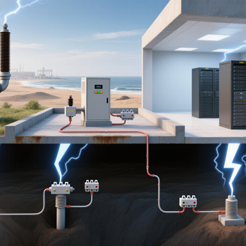
How to Choose the Right Lightning Arrester?

What a Lightning Arrester Is and How It Protects Electrical Systems

How to Choose the Right Lightning Arrester?

A lightning arrester is a protective device installed between conductors and earth. It normally presents high resistance, so operating voltage passes without significant leakage. During a surge, its metal-oxide elements conduct rapidly and redirect destructive energy to ground. The voltage then falls to a safer residual level. Simple in principle. Installation details decide its success.

The risk is substantial. The National Fire Protection Association reported an average of 22,600 lightning-related fires annually in the United States from 2014 to 2018. Those fires caused approximately 451 million dollars in direct property damage.

A suitable arrester should match the system’s maximum continuous operating voltage, grounding method, expected discharge current, and energy exposure.

IEC 62305-4 also emphasizes coordinated surge protection and short, low-inductance connections. Long connecting leads can create dangerous voltage during a fast impulse.

Selection should follow measured conditions, not guesswork.

Check altitude, pollution, temperature, enclosure location, and available fault current. For sensitive equipment, coordinate the arrester with upstream protection and equipment withstand ratings.

Field inspections often reveal loose earth connections or excessive cable bends. These small faults matter. A technically correct arrester can still underperform when grounding is poor.

The imperfect part is human judgment: lightning data can guide design, but local exposure may remain uncertain. Recheck the installation after major storms, equipment changes, or grounding work.

How to Assess Voltage, Current, and Surge Protection Requirements

How to Choose the Right Lightning Arrester?

Assess voltage before selecting a lightning arrester. Compare the system’s maximum continuous operating voltage with the arrester’s MCOV rating. It should tolerate normal voltage without conducting unnecessarily. Then check the protection level, or Up, against the insulation withstand level of connected equipment. A small margin matters near a motor control cabinet. IEEE C62.41.1 explains that surge exposure depends on installation location, wiring, and incoming disturbances. Outdoor service entrances face different conditions from indoor branch circuits.

Current ratings need equal attention. Nominal discharge current, In, indicates repeated surge capability. Impulse current, Iimp, addresses high-energy lightning currents. Do not choose only by the largest advertised peak. NOAA’s National Weather Service estimates that the United States experiences about 25 million lightning flashes annually, with roughly 20,000 ground strikes each day. Local exposure, building height, overhead lines, and grounding quality can raise risk. IEC 62305 recommends risk-based lightning assessment, not guesswork.

Tips:

Record operating voltage, grounding arrangement, cable length, and expected surge source. Select an arrester with suitable MCOV, Up, In, and Iimp values. Verify coordination between service entrance and downstream protection. Keep connecting leads short and straight; long bends add inductive voltage. A practical error is treating grounding as an afterthought. It is not. Even a correctly rated arrester can perform poorly with loose bonds, corroded terminals, or undersized conductors. Recheck the design after equipment changes.

How to Match Arrester Types with Electrical System Applications

How to Choose the Right Lightning Arrester?

Matching arrester types to electrical system applications requires more than checking nominal voltage. Start with the system’s maximum continuous operating voltage, grounding method, and temporary overvoltage exposure. A metal-oxide arrester must withstand normal voltage without conducting excessively. Ungrounded or resonant-grounded systems may require a higher continuous operating rating.

For overhead distribution lines, distribution-class arresters often provide practical protection for poles, transformers, and service equipment. Industrial feeders and smaller substations may need intermediate-class units with greater energy capability. Station-class arresters suit high-value transformers, generators, and high-voltage substations where fault current and switching energy can be severe. At cable-to-overhead transitions, place the arrester close to the cable termination. Long connecting leads reduce protection performance. That detail is easy to overlook.

Tips: Compare discharge energy, pressure-relief behavior, housing material, pollution level, altitude, and available fault current. Follow applicable electrical standards and the equipment manufacturer’s insulation-coordination data. Inspect grounding connections carefully; a loose, corroded connection can undermine an otherwise correct selection. Field conditions sometimes differ from drawings. Recheck them. I would also question any choice based only on “the usual voltage.” That shortcut can fail when system grounding or temporary overvoltage conditions change.

How to Choose the Right Lightning Arrester?

Match the arrester construction and energy capability to the electrical system voltage, grounding method, exposure level, and equipment insulation.

Selection guide: Low-voltage installations typically use MOV-based Type 2 or Type 1+2 SPDs. Medium-voltage distribution systems commonly use gapless metal-oxide distribution arresters. Subtransmission and transmission systems generally require higher-energy station or line arresters, coordinated with insulation levels and system grounding.

Voltage points shown are common nominal system-voltage examples: 0.4 kV, 13.8 kV, 69 kV, 230 kV, and 400 kV. The actual arrester MCOV and energy rating must be selected from the system’s maximum continuous line-to-ground voltage, temporary overvoltage conditions, lightning exposure, and applicable standards.

How to Compare Ratings, Materials, and Installation Conditions

Choosing a lightning arrester starts with system voltage, not appearance. Compare the arrester’s maximum continuous operating voltage with the actual phase-to-ground voltage. Then check nominal discharge current and energy capability against local lightning exposure.

Numbers matter. A higher rating is not always better. Excessive voltage protection may fail to protect sensitive equipment, while an undersized arrester can overheat during repeated surges. Review temporary overvoltage conditions, short-circuit capacity, and coordination with upstream protection. Standards such as IEC 60099-4 and IEC 61643-11 provide useful testing references, but field conditions still require engineering judgment.

Material selection affects service life. Zinc oxide varistors provide fast, nonlinear voltage limiting without gaps. Polymer housings resist moisture and impact, while porcelain offers strong mechanical stability but can break under severe stress. Consider ultraviolet exposure, salt, dust, temperature, and altitude.

Installation details often decide performance. Keep phase and grounding leads short and straight; every extra bend adds inductive voltage. Install the arrester close to the equipment it protects, with secure bonding to a low-impedance grounding system. Check clearances, enclosure ratings, thermal disconnection, and visible failure indication.

I have seen installations with excellent ratings fail because grounding paths were long and loosely terminated. That detail is easy to miss. Site inspection should include cable routing, torque verification, insulation condition, and signs of moisture. A careful design may still need revision after measuring the real installation.

How to Verify Arrester Quality, Maintenance Needs, and Service Life

Choosing a lightning arrester requires more than comparing purchase prices. Verify compliance with IEC 60099-4 or IEEE C62.11. Ask for type-test and routine-test records. These should include residual voltage, reference voltage, sealing, and energy-duty performance. Check the arrester’s line-discharge class against the system’s fault level and exposure.

Quality is visible in details. Examine the housing for cracks, chalking, moisture paths, or uneven sheds. Confirm that terminals fit tightly and that the pressure-relief device remains unobstructed. CIGRE Technical Brochure 549 warns that leakage-current readings can change with temperature, surface contamination, and harmonics. Therefore, one reading cannot prove arrester health. Compare readings over time, preferably under similar weather conditions. Thermographic inspections can reveal abnormal heating, but they should support electrical testing, not replace it.

Maintenance intervals should reflect local lightning density, pollution, switching activity, and recorded duty. The World Meteorological Organization reports that lightning occurs worldwide every day, while regional exposure varies sharply. Keep surge counters, inspection dates, and fault records together. A rising count deserves investigation. Service life is not a fixed calendar number. IEC testing evaluates accelerated electrical and environmental stresses, but field aging remains site-dependent. Some arresters operate reliably for decades; others deteriorate early after repeated high-energy events. I have seen maintenance plans fail because they trusted age alone. That assumption needs challenging. Examine the evidence.

How to Choose the Right Lightning Arrester? - How to Verify Arrester Quality, Maintenance Needs, and Service Life
Application / System Voltage Recommended Arrester Configuration Important Selection Data How to Verify Product Quality Routine Maintenance Requirements Typical Service-Life Expectation Replacement Indicators
Low-voltage AC systems
120/208 V to 277/480 V
Type 1 or Type 2 surge protective device, depending on installation location and available fault current. Uc / MCOV: suitable for the highest continuous line-to-ground voltage.
Nominal discharge current: commonly 5–20 kA for general commercial applications.
Protection level: select the lowest practical Up value compatible with the equipment.
Check the marked voltage ratings, short-circuit current rating, operating status indicator, thermal disconnector, enclosure rating, and compliance with the applicable installation standard. Inspect status indicators during scheduled electrical inspections. Confirm tight connections, absence of overheating, and intact enclosure seals. Replace modules or the complete device when the indicator shows failure. Commonly about 5–15 years, but actual life depends strongly on surge frequency, temporary overvoltage, installation environment, and system exposure. Red or failed status indicator, cracked housing, discoloration, melted terminals, repeated nuisance disconnection, water ingress, or evidence of a surge event.
Medium-voltage distribution
3.3–36 kV class systems
Metal-oxide gapless arrester connected phase-to-ground, normally installed at transformer, feeder, cable, and line transition points. MCOV: must exceed the maximum continuous line-to-ground voltage.
Rated voltage: selected according to temporary overvoltage conditions and system grounding.
Nominal discharge current: commonly 5 or 10 kA for distribution applications.
Verify nameplate data, rated voltage, MCOV, discharge-current class, pressure-relief capability, polymer or porcelain housing condition, leakage-current test data, and conformity with the applicable arrester standard. Perform periodic visual inspection, grounding and bonding checks, infrared inspection where appropriate, and leakage-current or watt-loss testing when required by the asset-management program. Keep the arrester clean and dry. Often about 10–20 years under normal service conditions. Severe contamination, moisture, lightning activity, or repeated temporary overvoltage can shorten this period. Increased resistive leakage current, abnormal watt loss, cracked or damaged housing, corrosion, loose grounding connection, tracking, puncture, or a history of severe overvoltage.
Medium-voltage industrial equipment
Motors, transformers, drives, and capacitors
Arrester selected for the equipment insulation level and the specific switching and operating environment. Consider system grounding, motor or transformer insulation withstand, switching-surges, cable length, motor-starting conditions, harmonic environment, and available fault current. Confirm that the arrester protection level is coordinated with the equipment basic insulation level. Review test certificates, production traceability, sealing quality, and thermal-disconnector operation. Inspect during planned shutdowns. Check cable terminations, grounding conductors, contamination, signs of partial discharge, and temperature differences between phases. Use trend data rather than relying on one measurement. Typically 10–20 years, although frequent switching surges and high operating temperatures may require earlier replacement. Progressive leakage-current increase, thermal hot spots, partial-discharge evidence, insulation damage, repeated fuse operation, or any visible sign of internal failure.
Overhead distribution lines
Lightning-exposed locations
Line surge arrester mounted close to the protected transformer, equipment, or line structure; use suitable mechanical and environmental protection. Evaluate lightning density, line exposure, grounding resistance, insulation coordination, energy capability, mechanical strength, and contamination severity. Inspect housing material, shed condition, connection hardware, grading rings where applicable, disconnector condition, and evidence of flashover or weathering. Confirm correct installation clearances. Carry out visual inspection after major storms and during routine line patrols. Check for broken sheds, displaced hardware, corrosion, animal damage, and poor grounding connections. Frequently about 10–20 years, but repeated lightning discharge can cause damage before the calendar life is reached. Arrester separation, broken housing, burn marks, flashover traces, damaged line hardware, failed disconnector, or a documented high-energy lightning event.
Substation and transmission applications
Above 36 kV
Station-class or line-discharge-class metal-oxide arrester selected through insulation coordination and system studies. Consider MCOV, rated voltage, switching-surge energy, lightning-surge energy, protective level, line-discharge class, system grounding, and temporary overvoltage duration. Review type-test and routine-test documentation, energy-duty capability, pressure-relief performance, seismic and mechanical ratings, housing integrity, and factory identification records. Establish a condition-based maintenance program. Use visual inspection, infrared thermography, leakage-current monitoring, grounding checks, and periodic comparison with historical measurements. Commonly about 15–30 years when correctly selected and operated. Service life is condition-dependent and should not be treated as a guaranteed replacement interval. A sustained rise in resistive leakage current or watt loss, abnormal thermal pattern, housing deterioration, seal failure, grounding problems, or results outside the manufacturer’s or utility’s limits.
Polluted, coastal, humid, or high-altitude environments Arrester with appropriate creepage distance, housing material, sealing, pollution performance, and altitude correction. Assess salt, dust, chemicals, condensation, ultraviolet exposure, ice, altitude, and enclosure ventilation. Confirm that clearances and creepage distances are adequate for the site. Check enclosure and housing IP or environmental rating, hydrophobicity where relevant, corrosion resistance, creepage distance, sealing, and test documentation for environmental durability. Increase inspection frequency. Clean only according to the approved procedure, remove contamination safely, check for tracking and erosion, and inspect seals and mounting hardware. Often shorter than normal service conditions: approximately 5–15 years for heavily exposed installations unless protection and maintenance are well controlled. Surface tracking, chalking, erosion, salt deposits, corrosion, moisture inside the enclosure, repeated leakage-current alarms, or loss of housing hydrophobicity.
All arrester types Use a coordinated protection system rather than selecting an arrester by voltage rating alone. Confirm system voltage, grounding method, MCOV, temporary overvoltage, prospective fault current, protection level, energy capability, installation lead length, and equipment insulation level. Require complete nameplate information, applicable standard references, routine-test records, traceable serial or batch information, installation instructions, and credible independent or accredited test evidence. Maintain inspection records, test results, surge history, environmental conditions, and replacement dates. Never touch or test an energized arrester without an approved electrical-safety procedure. There is no universal fixed life. A practical planning range is 5–30 years, depending on arrester type, surge exposure, temperature, contamination, moisture, and correct application. Any unsafe physical damage, failed indicator, abnormal leakage or temperature trend, confirmed high-energy discharge, insulation failure, or test result outside the defined acceptance criteria.
Selection note: MCOV must be suitable for the highest continuous operating voltage, while rated voltage must account for temporary overvoltage. Final selection should be verified through insulation coordination, system-grounding analysis, and the applicable electrical standard. Service-life values are typical planning ranges, not guaranteed lifetimes.

FAQS

How should I compare system voltage with an arrester’s rating?

Compare the maximum continuous operating voltage with the actual phase-to-ground voltage. The arrester should tolerate normal voltage without conducting unnecessarily. Check temporary overvoltage conditions too. Do not guess.

What does the protection level mean?

The protection level, or Up, shows the voltage remaining during a surge. Compare it with the connected equipment’s insulation withstand level. A small margin matters near motor controls and sensitive electronics. That detail matters.

How do In and Iimp differ?

Nominal discharge current, or In, describes repeated surge capability. Impulse current, or Iimp, addresses severe, high-energy lightning events. Choose both values according to local exposure and system conditions. Peak numbers can mislead.

What site conditions affect arrester selection?

Consider building height, overhead lines, cable length, grounding quality, and local lightning activity. Outdoor service entrances usually face greater exposure than indoor branch circuits. Pollution, salt, dust, temperature, and altitude also affect performance. Conditions vary sharply.

Why is grounding so important?

A suitable arrester can perform poorly with long, loose, or corroded grounding connections. Keep phase and grounding leads short and straight. Use secure bonds and adequately sized conductors. Keep it short.

Where should an arrester be installed?

Install it close to the equipment being protected. Long bends add inductive voltage during fast surges. Check clearances, enclosure protection, thermal disconnection, and visible failure indication. Routing deserves attention.

Which housing materials should I consider?

Polymer housings resist moisture and impact. Porcelain offers strong mechanical stability but may break under severe stress. Material choice should match ultraviolet exposure, pollution, temperature, and installation location. Appearance is not enough.

How can I verify quality and remaining service life?

Request independent type-test and routine-test records for residual voltage, sealing, and energy performance. Inspect for cracks, chalking, moisture paths, uneven sheds, and loose terminals. Track leakage current, surge counts, inspections, and fault history over time. One reading proves little.

How often should maintenance be performed?

Set inspection intervals according to lightning density, pollution, switching activity, and recorded surge duty. Thermal imaging can reveal abnormal heating, but it should support electrical testing. Service life is not simply a calendar number. Age alone can mislead.

Conclusion

Choosing the right Lightning Arrester is essential for protecting electrical systems from transient overvoltage caused by lightning and switching events. The selection process begins with understanding how the arrester diverts excess energy safely to ground while limiting voltage to a level equipment can withstand. Evaluate the system’s operating voltage, fault current, grounding arrangement, expected surge intensity, and the sensitivity of connected equipment before choosing a suitable protection level.

Different arrester types are designed for different applications, including power distribution, industrial equipment, control panels, and sensitive electronic systems. Compare continuous operating voltage, discharge capability, energy rating, enclosure materials, and compatibility with indoor or outdoor installation conditions. Environmental factors such as humidity, pollution, temperature, vibration, and available space should also be considered. Finally, verify product quality through technical documentation, testing records, and compliance information. A practical maintenance plan, clear inspection requirements, and an expected service life will help ensure reliable, long-term surge protection.

Madeline

Madeline

Madeline is a dedicated marketing professional with a wealth of expertise in our company's core offerings. With a keen understanding of the industry, she brings a unique perspective to her role, consistently delivering high-quality content that highlights the superior aspects of our products. As......