 Dehler
Dehler
Dehler
Choosing an Electrical Isolator in 2026 requires more than matching voltage and current numbers. It demands a clear view of the installation, its hazards, and its maintenance routine. An isolator should separate equipment safely, provide dependable mechanical operation, and make the circuit status visible. That small red handle matters.
John Cadick, an electrical safety author and consultant, offers a useful principle: “Isolation is a process, not merely a switch position.” His point remains practical. A correctly selected device must support safe switching, locking, testing, and restoration. The enclosure should also suit its surroundings. Dust, moisture, heat, corrosion, and accidental contact can quickly expose a weak choice.
Start with the system details. Check the rated operational voltage, continuous current, short-circuit withstand, number of poles, and utilization category. IEC 60947-3 is a valuable reference for low-voltage switchgear. Local electrical rules still control the final decision. Do not treat a general-purpose isolator as a load-breaking device without checking its rating. That mistake can damage contacts or create dangerous arcing.
Installation location changes everything. A rooftop unit may need UV resistance and a high IP rating. A workshop isolator may need a robust enclosure and padlock provision. Three-phase motors often require all live conductors to disconnect together. Yet no checklist is perfect. Labels fade. Covers crack. People improvise. Reviewing the actual site, not only the datasheet, remains essential. A qualified electrician should verify compatibility before purchase and commissioning.
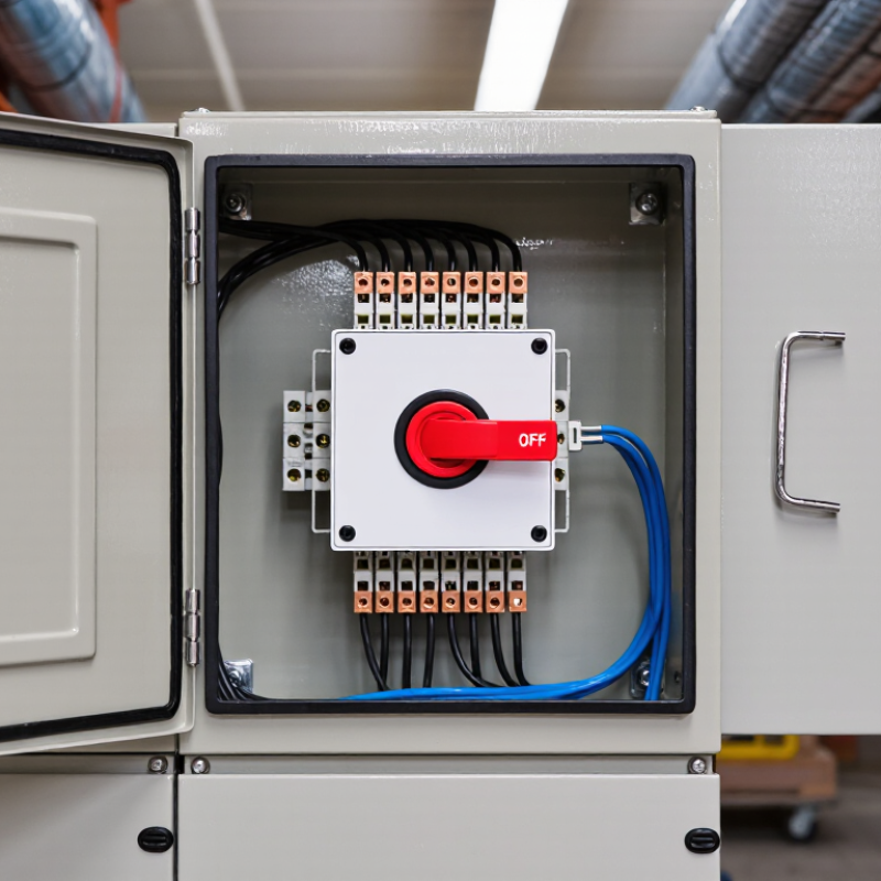
An electrical isolator creates a clear, controlled separation between a circuit and its power source. It supports safe maintenance, inspection, and emergency shutdown. It is not automatically a load-switching device. Some isolators must operate only after the circuit is de-energized.
The main types include switch-disconnectors, fuse-switch disconnectors, and DC isolators. A switch-disconnector combines isolation with load interruption when properly rated. A fuse-switch disconnector adds overcurrent protection. DC isolators need special attention because direct current can sustain an arc longer. Photovoltaic arrays, battery rooms, and industrial control panels often require dedicated DC designs.
Choose by voltage, current, pole configuration, fault level, and utilization category. Check whether the enclosure suits dust, moisture, heat, or outdoor exposure. An IP rating alone does not solve every environmental problem. The device should also support secure locking and clear position indication. The IEA Electricity 2024 report expects global electricity demand to grow by about 4% annually through 2026, increasing pressure on reliable isolation across expanding electrical systems. IEC 60947-3 remains a useful reference for low-voltage switch-disconnectors. Still, selection is rarely perfect. A unit may meet its current rating yet fail the installation’s short-circuit coordination. That detail deserves another review.
| Selection Dimension | What to Check | Common Options or Values | Why It Matters | Practical Selection Guidance |
|---|---|---|---|---|
| Primary purpose | Whether the device is intended for safe isolation, switching, or both. | Isolation only; load switching; emergency or maintenance switching. | An isolator creates a clearly separated circuit so equipment can be safely inspected or maintained. | Confirm that the product is suitable for isolation and that the installation includes an appropriate protective device for overload and short-circuit protection. |
| Applicable standard | The product standard and local installation requirements. | IEC 60947-3 is commonly used for low-voltage switch-disconnectors, disconnectors, and fuse-combination units. | Standards define requirements such as ratings, insulation, temperature rise, switching performance, and verification. | Use the current edition adopted by the authority having jurisdiction and follow the applicable national wiring rules. |
| Rated operational voltage (Ue) | The voltage of the circuit where the isolator will operate. | Typical low-voltage systems include 120 V, 230 V, 240 V, 400 V, and 415 V AC, depending on the electrical system. | The isolator must be rated for the circuit voltage and insulation conditions. | Never select only by physical fit. Verify the exact AC or DC voltage rating and the applicable frequency. |
| Rated current (Ie or In) | The continuous current expected under normal operating conditions. | Examples include 16 A, 20 A, 32 A, 40 A, 63 A, 80 A, 100 A, and higher ratings. | An undersized device may overheat, while an oversized device may not suit the connected equipment or protective scheme. | Choose a rating at least suitable for the calculated design current, while coordinating it with cables, protective devices, and local rules. |
| Number of poles | Which conductors must be disconnected. | 1-pole, 2-pole, 3-pole, 4-pole, or more poles for specialized systems. | Switching the required conductors helps prevent unexpected energization during maintenance. | Use 2-pole isolation where line and neutral disconnection is required; use 3-pole or 4-pole arrangements for suitable three-phase systems. |
| Neutral switching | Whether the neutral conductor must be disconnected with the live conductors. | Neutral switched; neutral solid; switched neutral with suitable contact sequencing. | Some installations require complete separation from the supply, while others specify that the neutral must remain connected. | Follow the wiring standard and system earthing arrangement. Do not switch a protective earth conductor as a substitute for isolation. |
| AC or DC application | The type of current and the circuit polarity. | AC distribution; photovoltaic DC; battery systems; control circuits. | DC arcs are more difficult to extinguish than AC arcs because the current does not naturally pass through zero. | Use an isolator specifically rated for the required DC voltage, current, polarity, and number of series-connected poles. |
| Utilization category | The type of load being switched. | Resistive loads; mixed distribution loads; motors; transformers; capacitive or electronic loads. | Motors and other inductive loads can produce higher switching stress than simple resistive loads. | Check the manufacturer-declared utilization category and ensure it matches the actual load, especially for motors and high-inrush equipment. |
| Short-circuit coordination | The prospective fault current and upstream protective device. | Coordination with a fuse or circuit breaker; conditional short-circuit rating where specified. | An isolator is not automatically a short-circuit protective device. | Verify the assembly’s short-circuit withstand or conditional rating and coordinate it with the upstream protective device. |
| Installation location | Indoor, outdoor, wet, dusty, corrosive, or restricted-access environment. | Indoor enclosure; weather-resistant enclosure; industrial enclosure; hazardous-area equipment where applicable. | Environmental conditions can affect insulation, corrosion resistance, mechanical operation, and service life. | Choose an enclosure with an appropriate IP rating and material. Outdoor equipment usually requires protection against water, dust, UV exposure, and temperature changes. |
| Ingress protection (IP) | Protection against solid objects and water. | IP20 for basic indoor protection; IP44 for protection against splashing water; IP65 for dust-tight and water-jet protection, when correctly installed. | The IP code applies to the complete installed enclosure and its cable-entry arrangement. | Select the IP level based on the actual environment, then maintain the rating with suitable glands, covers, and mounting practices. |
| Visible isolation | Whether the open position can be visually confirmed. | Visible blade or contact position; clear handle indication; enclosed mechanism with positive position indication. | Clear status indication reduces the risk of working on an energized circuit. | For maintenance-critical equipment, prefer a design with a clear ON/OFF indication and a means of securing the OFF position. |
| Lockout capability | Whether the isolator can be locked in the OFF position. | Padlockable handle; lockable enclosure; multiple-person lockout provision. | Lockout prevents unauthorized or accidental re-energization during maintenance. | Confirm that the locking method is compatible with the site’s isolation and lockout/tagout procedure. |
| Mounting method | How the device will be installed and accessed. | Distribution-board mounting; DIN-rail mounting; panel mounting; surface mounting; enclosure mounting. | Correct mounting supports safe operation, heat dissipation, cable routing, and maintenance access. | Check terminal orientation, available space, cable bending radius, torque requirements, and accessibility before installation. |
| Terminal and conductor compatibility | Cable size, conductor material, terminal type, and tightening torque. | Solid or stranded copper conductors; specified cross-sectional area; compatible lugs or ferrules. | Incorrect conductor preparation or loose terminals can cause overheating and failure. | Use only the permitted conductor size and type, strip length, accessories, and torque stated in the product documentation. |
| Frequency | The operating frequency of the circuit. | 50 Hz; 60 Hz; or a declared range. | Electrical and switching performance can depend on the rated frequency. | Ensure the isolator’s declared rating covers the system frequency, especially in motor and industrial applications. |
| Temperature and derating | Ambient temperature, enclosure temperature, altitude, and grouping. | Normal indoor ambient conditions; elevated temperature; multiple devices installed side by side. | Heat buildup can reduce the permissible continuous current and shorten service life. | Apply the relevant derating information for ambient temperature, enclosure ventilation, altitude, and adjacent devices. |
| Application type | The equipment or circuit that needs isolation. | Lighting circuit; socket circuit; HVAC unit; motor; generator; photovoltaic array; battery storage; machinery. | Different loads and energy sources create different switching, isolation, and safety requirements. | Identify all possible sources of energy, including back-feed from generators, inverters, batteries, and control circuits. |
| Maintenance and inspection | Access for testing, cleaning, tightening, and functional checks. | Accessible handle; clear labels; serviceable enclosure; documented inspection interval. | Reliable isolation depends on correct operation and a maintained installation. | Label the isolator, keep it accessible, inspect for heat damage or wear, and test according to the maintenance plan and local requirements. |
| Safety verification | Whether the circuit is actually de-energized before work begins. | Switch OFF; lock and tag; test for absence of voltage; verify the test instrument. | Mechanical isolation alone does not replace safe electrical work procedures. | Use an approved isolation procedure: identify all sources, isolate, lock and label, prove the tester, test the circuit, and re-prove the tester. |
It separates a circuit from its power source. This supports maintenance, inspection, and emergency shutdown. It is not automatically an overload protection device.
No. Some isolators operate only after the circuit is de-energized. A properly rated switch-disconnector can interrupt certain loads safely. Check the device rating before switching.
Common types include switch-disconnectors, fuse-switch disconnectors, and DC isolators. A fuse-switch disconnector adds overcurrent protection. DC isolators suit photovoltaic arrays, battery rooms, and control panels.
Direct current can sustain an electrical arc for longer. The isolator needs suitable DC ratings and pole arrangements. Never assume an AC device works safely on DC.
Check voltage, current, poles, switching frequency, and fault level. Also confirm the utilization category and short-circuit withstand rating. A current rating alone is not enough.
No. An IP rating mainly addresses solid particles and water entry. Sunlight, corrosion, chemicals, vibration, and temperature need separate review. Small sealing gaps can still cause trouble.
A dry indoor room needs different protection from an exposed rooftop. Measure cable-entry direction, mounting space, and handle clearance. Leave enough room for cable bending. That detail is often underestimated.
Choose clear position markings, durable terminals, and a lockable handle. The isolator should remain reachable without unsafe climbing. A locked handle helps prevent unintended operation. It is helpful, not foolproof.
Review technical documents, test records, certification, and environmental ratings. Inspect terminal torque, cable glands, covers, and enclosure sealing. Ask a qualified electrician to verify isolation points and earthing. Labels alone do not prove suitability.
Site conditions can change through heat, moisture, dust, vibration, or equipment upgrades. The original choice may no longer suit the circuit. Review it again. Selection is rarely perfect.
Choosing the right Electrical Isolator in 2026 requires more than selecting a device with a suitable appearance or price. First, understand its purpose and choose the appropriate type for the circuit, such as a single-pole, double-pole, or multi-pole isolator. Carefully evaluate the system voltage, operating current, number of poles, and required isolation level to ensure safe and reliable disconnection during maintenance or emergencies.
Installation conditions are equally important. Consider indoor or outdoor use, available space, temperature, moisture, dust, and the required environmental protection rating. Compare safety standards, operating mechanisms, enclosure quality, labeling, and durability before making a decision. Select an isolator that matches the electrical system and installation environment, then ensure it is installed by a qualified professional according to applicable requirements. Regular inspection, cleaning, testing, and timely replacement of damaged components will help maintain dependable performance and long-term safety.
