
Dehler
The 2026 Moulded Circuit Breaker market is becoming more demanding. Global buyers now compare safety, breaking capacity, lifecycle cost, certification, and digital monitoring. Product labels alone cannot reveal whether a breaker suits a factory, data center, solar plant, or commercial building.
Electrical protection specialist Dr. Andreas W. Müller offers a practical reminder: “A breaker is reliable only when its protection settings match the real installation.” That principle matters. A compact Moulded Circuit Breaker may look suitable, yet fail to provide adequate short-circuit protection under actual network conditions. Cable size, ambient temperature, coordination, fault current, and enclosure design all influence the final choice.
Small details matter.
This guide examines the top Moulded Circuit Breaker types expected to attract global buyers in 2026. It compares thermal-magnetic, electronic-trip, adjustable, current-limiting, and motor-protection designs. It also considers voltage ratings, pole configurations, interrupting capacity, operating mechanisms, communication options, and maintenance needs. These factors affect both purchasing decisions and long-term electrical safety.
No product ranking is perfect. Buyer priorities differ between regions and applications. A low-cost breaker may reduce initial spending, but unsuitable accessories or difficult replacement procedures can increase ownership costs. Even experienced purchasing teams sometimes overlook local installation conditions. That weakness deserves attention.
The sections ahead focus on practical selection rather than marketing claims. They explain where each type performs well, where it may disappoint, and which specifications deserve verification before ordering. For international buyers, reliable documentation and traceable testing are just as important as price.
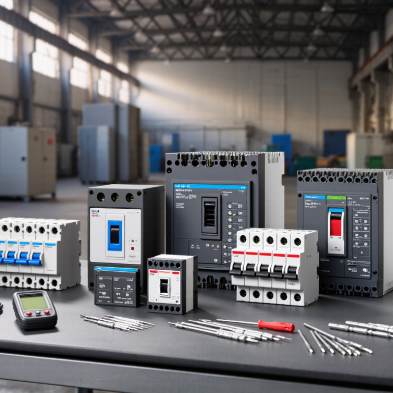
What Is a Moulded Case Circuit Breaker and How Does It Work?
A moulded case circuit breaker (MCCB) protects low-voltage circuits from overloads and short circuits. Its insulated moulded housing separates live conductors from the surrounding environment. Inside, a thermal element responds to prolonged overcurrent. A magnetic trip reacts almost instantly to severe fault current. Some advanced models use electronic sensing for more precise protection and adjustable settings.
When current exceeds the selected limit, the trip mechanism releases the contacts. An arc-control chamber then divides and cools the electrical arc. This action interrupts the fault safely and limits equipment damage. MCCBs commonly serve distribution boards, motors, commercial buildings, and industrial machines. The IEC 60947-2 standard defines important requirements for construction, testing, and operational performance.
Demand is becoming more practical, not merely larger. The International Energy Agency’s Electricity 2024 report expects global electricity demand to grow by about 4% annually through 2026. This growth increases the need for dependable protection in expanding networks. A 2024 market analysis by Grand View Research also identifies rising infrastructure investment as a key circuit-breaker market driver. Exact forecasts differ between reports. That difference matters.
For global buyers, interrupting capacity, rated current, pole configuration, trip characteristics, and ambient temperature require careful checking. A 400 A frame does not always mean a 400 A setting. Installation altitude and enclosure ventilation can also affect performance. Selection errors happen. A qualified engineer should verify coordination, cable capacity, and local compliance before purchase.
2026 Top Moulded Circuit Breaker Types for Global Buyers
Moulded case circuit breakers differ by design, trip method, and installation format. Thermal-magnetic MCCBs combine a delayed thermal trip with fast magnetic protection. They suit ordinary distribution panels and moderate fault levels. Electronic-trip MCCBs use sensors and processors. They offer adjustable overload, short-circuit, and ground-fault settings.
According to the IEA’s Electricity 2024 report, global electricity demand is expected to grow by about 4% annually through 2026. This growth increases demand for compact, selective protection in factories, buildings, and renewable-energy systems. Fixed MCCBs are economical and simple. Plug-in versions speed replacement. Draw-out designs support safer inspection and maintenance. Two-pole, three-pole, and four-pole models serve different system arrangements.
Current-limiting MCCBs reduce let-through energy during severe faults. High-breaking-capacity versions fit installations with larger prospective short-circuit currents. Adjustable electronic units help coordinate upstream and downstream protection, but settings require verified calculations. A larger frame does not automatically provide better protection. That assumption can create poor coordination.
For motor circuits, buyers should check magnetic pickup ranges and starting-current tolerance. For direct-current systems, polarity and arc-extinguishing design need special attention. Ratings must match voltage, frequency, ambient temperature, and enclosure conditions. IEC 60947-2 provides a widely used reference, but local certification still matters. Catalogue comparisons are useful. Field measurements remain essential.
Moulded case circuit breakers are commonly selected by their trip design and protection function. Thermal-magnetic models combine overload and short-circuit protection, while electronic-trip models provide adjustable protection and measurement functions. Current-limiting designs reduce let-through energy during severe faults, and motor-protection MCCBs are configured for motor starting and overload characteristics. The current values shown are representative upper ranges found in low-voltage MCCB product classes; exact ratings depend on the applicable IEC 60947-2 or UL 489 design and certification.
2026 Top Moulded Circuit Breaker Types for Global Buyers
Global buyers need protection details, not just ampere labels. The IEA Electricity 2024 report projects global electricity demand to grow by about 3.4% annually from 2024 to 2026. More distributed power means greater fault exposure.
Thermal-magnetic MCCBs suit common commercial and industrial feeders. Their thermal element responds to overloads. Their magnetic element reacts to short circuits. Electronic-trip MCCBs offer adjustable long-time, short-time, instantaneous, and ground-fault settings. They improve coordination between upstream and downstream devices. Adjustable protection matters.
Current-limiting MCCBs reduce let-through energy during severe faults. This can lower conductor and equipment stress. Residual-current or ground-fault modules add protection against leakage paths. They are valuable near wet areas, generators, and sensitive equipment.
Check the rated operational voltage, continuous current, poles, and interrupting capacity. Under IEC 60947-2, Icu shows ultimate short-circuit capacity, while Ics indicates service short-circuit performance. A higher Icu does not automatically mean better system coordination. UL 489 evaluations also emphasize tested interrupting ratings and enclosure conditions. In practice, a 400 A breaker may still be unsuitable if its available fault current exceeds its rating. Installation altitude, ambient temperature, cable size, and enclosure ventilation can change performance. I would not trust a neat specification sheet alone. Field verification is often the missing step.
Choosing a moulded case circuit breaker begins with the load, not the catalogue. Record system voltage, continuous current, poles, frequency, and prospective short-circuit current. A 250 A frame does not automatically suit a 250 A feeder. Cable size, ambient temperature, and installation method can reduce usable capacity. Heat matters. Check derating data at the actual panel temperature, especially in compact enclosures.
Select a trip unit that matches the application. Thermal-magnetic protection works well for many feeders and motors with moderate starting current. Electronic units can offer adjustable long-time, short-time, instantaneous, and ground-fault settings. For transformers, pumps, or compressors, compare inrush current with the instantaneous trip threshold. Otherwise, nuisance tripping may appear during startup. Interrupting capacity must meet the calculated fault level at the installation point. Do not rely on a typical value.
Review coordination with upstream and downstream protective devices. Selectivity can keep one branch offline while essential circuits remain energized. Confirm terminal sizes, busbar compatibility, mounting space, operating handle access, and auxiliary contact requirements. For outdoor or dusty locations, examine enclosure rating, corrosion resistance, and temperature limits. Verify testing and certification against requirements in the destination market. This step is often rushed. It should not be. A careful checklist, fault study, and final setting review reduce expensive surprises, although field conditions can still expose assumptions.
| MCCB Type | Typical Protection Method | Common Current Range | Typical Breaking-Capacity Range | Typical Applications | Main Advantages | Key Limitations | Selection Factors |
|---|---|---|---|---|---|---|---|
| Thermal-Magnetic MCCB | Thermal element for overload protection and magnetic element for short-circuit protection. | Approximately 16–800 A, depending on frame size and product series. | Approximately 18–100 kA at the rated operating voltage; the actual value must be checked on the product data sheet. | Commercial buildings, distribution boards, lighting feeders, socket circuits and general industrial loads. | Simple operation, widely available, cost-effective and usually easy to coordinate with downstream protective devices. | Thermal response changes with ambient temperature; fixed trip characteristics may limit precise coordination. | Load current, ambient temperature, prospective short-circuit current, cable ampacity and coordination requirements. |
| Electronic-Trip MCCB | Electronic sensing and processing for adjustable long-time, short-time, instantaneous and sometimes ground-fault protection. | Approximately 100–1600 A, with some ranges extending beyond this level. | Approximately 25–150 kA, depending on frame size, voltage and current-limiting design. | Large commercial facilities, data centers, industrial distribution, generators and critical power systems. | More accurate settings, improved selectivity, event information and better adaptability to changing loads. | Higher purchase cost; electronic accessories may require auxiliary power or specific installation conditions. | Required protection functions, selectivity study, system short-circuit level, communication needs and maintenance capability. |
| Adjustable-Trip MCCB | Trip thresholds can be adjusted within defined long-time, short-time or instantaneous ranges. | Approximately 100–1600 A, depending on the frame and trip unit. | Approximately 25–100 kA in common low-voltage distribution applications. | Multi-level distribution systems, industrial feeders, transformers and installations with variable operating conditions. | Supports better cable protection and coordination than fixed-trip devices when correctly configured. | Incorrect settings can reduce protection or cause nuisance trips; settings should be documented and verified. | Calculated design current, conductor rating, inrush current, upstream and downstream coordination, and available fault current. |
| Current-Limiting MCCB | Special contact, arc-control and operating mechanisms reduce the peak let-through current and energy during a fault. | Approximately 15–800 A in many low-voltage product families. | Often available with interrupting ratings of approximately 35–200 kA at specified voltages. | High-fault-level industrial systems, compact switchboards, motor control centers and installations requiring reduced arc energy. | Can reduce thermal and mechanical stress on cables, busbars and downstream equipment during short circuits. | Usually costs more; let-through data and coordination must be evaluated with the complete system. | Prospective fault current, peak let-through current, I²t energy, equipment withstand rating and selectivity. |
| Motor-Protection MCCB | Designed for motor feeder duty, with overload and short-circuit protection coordinated with motor starting characteristics. | Commonly about 16–800 A, selected according to motor full-load current and starting conditions. | Approximately 18–100 kA, subject to the rated voltage and specific configuration. | Pumps, fans, compressors, conveyors, machine tools and other three-phase motor feeders. | Better tolerance of motor starting current and improved coordination with contactors and overload relays. | It may not replace all required motor-control components; overload, phase-loss and earth-fault functions vary by design. | Motor full-load current, starting current, starting time, duty cycle, coordination class and local installation rules. |
| MCCB with Ground-Fault Protection | Detects residual or ground-fault current using an integrated or associated sensing system. | Approximately 100–1600 A for many distribution applications. | Approximately 25–100 kA, depending on the base MCCB and system voltage. | Industrial plants, large buildings, generators, service entrances and systems requiring enhanced fault protection. | Can improve protection against ground faults and support system-level protection coordination. | Ground-fault settings require careful coordination; leakage currents and grounding arrangements can affect operation. | Grounding system, required pickup and delay, leakage-current profile, personnel-safety requirements and local code. |
| Four-Pole MCCB | Protects and switches three phase conductors plus the neutral; neutral protection may be full-rated or reduced-rated. | Approximately 16–1600 A, depending on frame size and application. | Approximately 18–100 kA in typical low-voltage systems. | Three-phase four-wire systems, commercial buildings, data centers, generators and systems with switched neutrals. | Provides improved isolation and neutral management where the system design requires all conductors to be disconnected. | More expensive and larger than a three-pole unit; neutral switching must match the earthing and system design. | Neutral current, harmonic loads, earthing method, generator transfer arrangement and required isolation procedure. |
| DC-Rated MCCB | Uses a mechanism and arc-extinguishing system rated for direct-current interruption. | Commonly about 16–1000 A, depending on the number of poles and series connection. | Highly application-dependent; often specified by DC voltage, pole arrangement and fault-current level rather than AC kA alone. | Battery energy storage, photovoltaic combiner and feeder circuits, electric-vehicle infrastructure and industrial DC systems. | Suitable for DC circuits where the current does not naturally pass through zero as it does in AC systems. | An AC-only MCCB must not be assumed suitable for DC; polarity, voltage and pole-series requirements are critical. | Maximum DC voltage, continuous current, prospective DC fault current, polarity, pole configuration and cable arrangement. |
Global buyers should treat MCCB compliance as a selection requirement, not a marketing detail. The applicable standard depends on the installation market and product category. IEC 60947-2 is widely used for low-voltage circuit breakers, while UL 489 and CSA requirements may apply in North America. Certification should come from a recognized testing body. Check the certificate number, product family, rated voltage, and tested interrupting capacity. Details matter.
A reliable MCCB should match the system’s actual operating conditions. Confirm rated current, breaking capacity, pole configuration, trip characteristics, insulation voltage, and frequency.
For a factory panel, compare the breaker’s short-circuit rating with the available fault current. Do not rely only on the frame size. A compact device may still require a higher interrupting rating. Ambient temperature also matters, especially inside a crowded enclosure. Derating data should be clear and traceable.
Buyer review should include terminal compatibility, enclosure space, accessories, maintenance instructions, and replacement availability. Request routine test records and supporting documents, including inspection reports when required by the project. Labels should show essential ratings in a readable format.
Check the label. A certificate alone is not enough. Some purchasing teams overlook altitude, humidity, or coordination with upstream protection. That mistake can affect nuisance tripping and equipment safety.
Requirements also vary between countries, so local approval rules deserve verification before shipment. Even experienced buyers can miss small documentation gaps. A careful technical review is slower, but it reduces costly changes after installation.
It protects electrical circuits from overloads and short circuits. It can serve factories, buildings, and renewable-energy systems.
Its thermal element responds to prolonged overloads. Its magnetic element reacts quickly to short circuits. Simple and widely used.
It provides adjustable overload, short-circuit, and ground-fault settings. These adjustments can improve coordination between upstream and downstream protection.
Fixed models are economical and simple. Plug-in models support faster replacement. Draw-out models make inspection and maintenance safer.
Two-pole, three-pole, and four-pole models suit different system arrangements. The pole count must match the circuit design.
Check voltage, continuous current, frequency, poles, and interrupting capacity. Also review temperature, altitude, cables, and enclosure ventilation.
Icu indicates ultimate short-circuit capacity. Ics indicates service short-circuit performance. A higher Icu alone does not guarantee good coordination.
Yes, they reduce let-through energy during severe faults. This can lower stress on conductors and connected equipment.
Motor circuits need suitable magnetic pickup ranges and starting-current tolerance. Direct-current systems require correct polarity and arc-extinguishing design.
Not always. Field measurements remain essential. Available fault current may exceed a neat catalogue rating. That shortcut can mislead.
This guide explains what a Moulded Circuit Breaker is and how it protects low-voltage electrical systems by interrupting excessive current during overloads or short circuits. It introduces the main MCCB types according to their construction, operating method, trip technology, and intended function, helping buyers understand the differences between thermal-magnetic, electronic, adjustable, fixed, and specialized configurations.
The article also reviews essential ratings and protection features, including rated current, voltage, breaking capacity, trip settings, and coordination requirements. It outlines how to select the appropriate device based on load characteristics, system conditions, installation environment, future expansion, and maintenance needs. Finally, it summarizes important global standards, certification expectations, documentation requirements, and purchasing considerations, enabling international buyers to compare products responsibly and choose reliable protection for commercial, industrial, and infrastructure applications.
